Sheet metal tolerances define the acceptable variation from a nominal dimension in fabricated components. Because sheet metal parts are cut, bent, and formed rather than machined from solid material, each manufacturing step introduces natural variation.
Understanding achievable tolerances helps engineers:
- Design parts that assemble reliably
- Avoid unrealistic specifications
- Reduce quote delays and rework
- Balance precision with cost
The chart below summarizes typical tolerance capabilities in modern sheet metal fabrication. These values represent typical fabrication capability, not guaranteed limits for every geometry or material.
Sheet Metal Tolerance Chart
| Feature | Typical Tolerance | Notes for Designers |
|---|---|---|
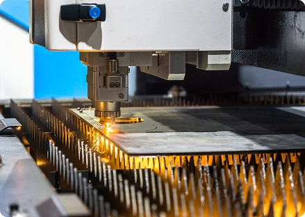
| Laser cutting profile tolerance | ±0.10–0.20 mm (±0.004–0.008 in) | Fiber laser cutting provides high precision for flat profiles and cutouts. |
| Hole diameter tolerance | ±0.10–0.15 mm | Smaller holes relative to thickness may require drilling or reaming for tighter tolerance. |
| Feature location tolerance | ±0.20–0.30 mm | Positional tolerance depends on sheet movement, thermal distortion, and machine accuracy. |
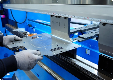
| Press brake bend angle | ±1° typical | A 90° bend may measure 89°–91° due to springback and tooling variation. |
| Flange length after bending | ±0.25–0.50 mm | Variation increases with multiple bends and thicker materials. |
| Inside bend radius | ±0.20–0.50 mm | Radius varies slightly due to tooling wear and material hardness. |
| Material thickness tolerance | ±0.05–0.30 mm depending on gauge | Mill tolerance varies by thickness and material specification. |
Process-Specific Tolerance Considerations
Laser Cutting
Laser cutting offers the highest dimensional accuracy in sheet metal fabrication. However, tolerances can vary due to material thickness, heat input, and sheet movement during cutting.
Typical capabilities:
- ±0.1 mm profile accuracy
- Very repeatable hole patterns
- Minimal distortion on thin materials
Press Brake Bending
Bending introduces the most dimensional variation in sheet metal parts. Because bending stretches material, final dimensions can vary slightly from the flat pattern.
Common variables include:
- Springback
- Material grain direction
- Tooling selection
- Material thickness
Typical bending tolerance:
- Angle: ±1°
- Flange length: ±0.25–0.50 mm
Weld Distortion Impact
Welding introduces thermal expansion and contraction that can distort sheet metal assemblies. If precision alignment is required, engineers should locate critical dimensions away from weld zones.
Potential effects include:
- Panel warping
- Hole misalignment
- Dimensional drift in welded frames
Mitigation strategies:
- Balanced weld sequencing
- Fixturing during welding
- Post-weld machining for critical features
Tolerance Stacking in Multi-Bend Parts
Tolerance stacking occurs when small variations accumulate across multiple features.
Example:
A bracket with four bends may experience variation from:
- Laser cut tolerance
- Bend angle tolerance
- Flange length variation
Even when each step is within specification, the total deviation can affect assembly.This is a common cause of misaligned mounting holes, poor enclosure fit, and assembly interference.
Designers should prioritize functional dimensions rather than applying tight tolerances everywhere.
When Secondary Machining Is Required
Some sheet metal features require tighter tolerances than fabrication processes can achieve.
Secondary machining may be required when:
- Hole tolerances tighter than ±0.05 mm are needed
- Precision alignment pins are used
- Bearings or press-fit hardware are involved
- Surface flatness is critical
Typical secondary processes include:
- CNC drilling
- Reaming
- Tapping
- Milling
Tolerance vs. Cost Relationship
Tolerance specifications strongly influence fabrication cost. Overly tight tolerances can dramatically increase cost because they require:
- Slower machine speeds
- Specialized tooling
- Additional inspection steps
Engineers should apply tight tolerances only to critical features. Here’s a general chart to help you review your options:
| Tolerance Range | Manufacturing Impact |
|---|---|
| ±0.50 mm | Easily achievable, lowest cost |
| ±0.20 mm | Standard fabrication tolerance |
| ±0.10 mm | Requires careful setup and inspection |
| ±0.05 mm or tighter | May require secondary machining |
Best Practices for Specifying Sheet Metal Tolerances
When preparing fabrication drawings:
Specify tight tolerances only where function requires it
Use general tolerance standards (ISO 2768 or ASME Y14.5) for non-critical features
Consider tolerance stacking in multi-bend parts
Avoid placing precision features near bends or welds
Consult fabricators during design for manufacturability
Working With Budde Sheet Metal Works
Budde Sheet Metal Works works closely with engineers to optimize tolerance strategies during the design phase.
Our engineering team can help with:
- Design for manufacturability (DFM) reviews
- Tolerance analysis for assemblies
- Material and forming recommendations
- Prototype and production fabrication
If you are unsure whether a tolerance is achievable, our team can review your design before quoting.