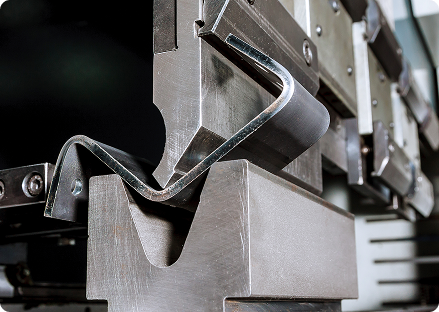
• About
  • Custom Sheet Metal Fabrication
  • CNC Fabrication
    • Blog

  • Gallery

Designing for Press Brake Forming

A Practical Guide for Engineers

Press brake forming is one of the most common sheet metal fabrication processes. It uses a punch and die to bend flat sheet metal into the desired geometry. The sheet is clamped between a top punch and bottom die and bent to a controlled angle.


Parts designed with press brake capabilities in mind are easier to manufacture, faster to quote, and more consistent in production.


This guide outlines key principles that will help engineers design sheet metal parts optimized for press brake forming.

Overview: Understanding Press Brake Bending Methods

Air Bending

Air bending is the most common press brake bending method, and because of its flexibility, air bending is used for most sheet metal fabrication work.


Highlights of Air Bending:


  • The punch presses the material into the V-die
  • The sheet does not fully contact the die bottom
  • The final angle is controlled by punch depth


Advantages:


  • Lower forming force
  • Flexible bend angles
  • Reduced tooling requirements

Bottom Bending (Bottoming)

Bottom bending (also called bottoming) is a press brake bending method where the sheet metal is pressed firmly into the die cavity. Because the material fully contacts the die, the bend angle is primarily determined by the tooling geometry rather than punch depth.


Highlights of Bottom Bending:


  • The punch forces the sheet metal fully into the V-die
  • The material makes full contact with the die surfaces
  • The final bend angle is controlled by the die angle


Advantages:


  • More consistent bend angles
  • Reduced springback compared to air bending
  • Better repeatability for high-volume production

Tooling Limitations and Design Constraints

Press brake tooling determines what geometries can be formed. Because tooling physically contacts the part during forming, certain geometries may:


  • Interfere with tooling
  • Prevent full punch travel
  • Require special tools


Key limitations include:


  • Punch and die geometry
  • Die opening width
  • Backgauge clearance
  • Tool interference with adjacent features


Understanding these constraints early in design reduces costly redesigns or tooling changes during quoting.

Minimum Flange Length Requirements

Flanges must be long enough to rest securely on the press brake die shoulders during forming.


A widely accepted rule of thumb is: Minimum flange length ≈ 4 × material thickness


For some tooling setups, 6 × material thickness provides more stable forming.

Example Minimum Flange Length

Material ThicknessRecommended Minimum Flange
1 mm4–6 mm
2 mm8–12 mm
3 mm12–18 mm

If you wanted to try and manufacture flanges shorter than this, you could experience slippage during forming, distortion, and special tooling requirements

Inside Bend Radius Selection

The inside bend radius determines how tightly the material can bend without cracking and thicker materials require larger radii because they resist deformation more strongly.

Choosing the appropriate bend radio is important because it improves:


  • Material integrity
  • Surface finish
  • Dimensional consistency

Typical guidelines

Material ThicknessRecommended Inside Radius
1–6 mm≈ 1 × thickness
6–12 mm≈ 1.5 × thickness
>12 mm2–3 × thickness

Springback Behavior by Material

After bending, sheet metal tends to partially return toward its original shape. This phenomenon is called springback.


Understanding springback helps engineers anticipate final bend angles and dimensional variation.


Springback increases with higher material strength, larger bend radius, and thinner materials.

Typical guidelines

MaterialSpringback Behavior
Mild steelLow to moderate
Stainless steelHigh
AluminiumModerate
High-strength steelsVery high

*Note that fabricators typically overbend slightly during forming to compensate for springback.

Press Brake Design Constraints Reference Chart

Design FeatureWhy It’s ChallengingCommon IssuesPractical Guidance
Deep Channels & Box FormsDeep channel geometries restrict tool access and punch reach during bending.• Tool interference
• Limited punch reach
• Backgauge positioning difficulties
• Ensure sufficient clearance for punch and die tooling
• Avoid channels that are extremely narrow relative to their depth
• Consider splitting complex shapes into multiple parts and welding them after forming
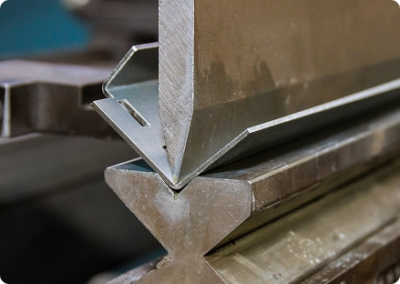
Return FlangesReturn flanges bend back toward the part, limiting punch and die access during forming.• Punch clearance issues
• Die interference
• Restricted tool access angles
• Maintain adequate spacing between adjacent bends
• Avoid extremely tight return geometries
• If necessary, redesign geometry to reduce tooling interference
Hem FeaturesHems require folding the material over itself, which increases material thickness and requires staged forming.• Wrinkling during folding
• Inconsistent edge quality
• Tool interference during secondary forming
• Account for increased thickness after hemming
• Ensure adequate clearance for forming tools
• Design hem length to support the forming sequence
Forming Sequence (Multi-Bend Parts)Multiple bends must be performed in a specific order to avoid tool collisions or blocked features.• Early bends blocking later bends
• Backgauge access problems
• Tool collisions during forming
• Design bends so each step remains accessible to tooling
• Maintain clearance for backgauge positioning
• Simplify bend order where possible
Special Tooling RequirementsCertain geometries cannot be formed with standard press brake tooling.• Increased setup time
• Additional tooling costs
• Longer lead times
• Avoid tight-radius bends, short flanges, or deep channels where possible
• Design parts to work with standard tooling when feasible

Common Press Brake Design Mistakes

It’s not uncommon for engineers to encounter these challenges during press brake fabrication.

01

Flanges Too Short

Short flanges cannot rest on die shoulders, making stable forming impossible.

02

Holes Too Close to Bends

Features near bend lines can distort during forming.

03

Overly Tight Radii

Small radii can cause cracking or require excessive forming force.

04

Tooling Interference

Deep channels or return flanges may prevent punch access.

05

Ignoring Forming Sequence

Multiple bends can block each other if the sequence isn’t considered.

Checklist: Designing for Efficient Fabrication

Parts designed for press brake forming should follow these principles to the best performance and precision.

Minimum flange length ≥ 4× material thickness

Inside bend radius ≥ material thickness

Adequate clearance for tooling

Features located away from bend lines

Multi-bend parts designed with forming sequence in mind

Avoid geometries that require special tooling unless necessary

Partner With Budde During the Design Phase

The most successful sheet metal parts are developed with fabrication constraints in mind.


Budde Sheet Metal Works collaborates with engineers to:


  • Review designs for manufacturability
  • Optimize bend geometry
  • Identify tooling constraints early
  • Improve cost efficiency and production reliability


If you’re unsure whether a design will form correctly, our engineering team can review your CAD files before quoting.